Liam Wynn
This is my site. Here, I make neato projects and blog posts.
Implementing a Ray Caster Part 2: Sprite Rendering
Welcome back. In this part, we will explore sprite rendering. Originally, I was going to do floor, ceiling, and skybox rendering for this part. The reason being was that in my implementation, I did floors, ceilings and sky rendering after wall rendering. However, sprite rendering is a fundamental part of the overall rendering system. We use sprites to render objects in worlds. Things like trees, pots, tables, and so on cannot be done well without sprites.
Before we get started, I would like to direct you to a post by one David Layne. I will admit, when I first did my implementation, I used this and didn’t understand why it worked. So pretty much all credit goes to him. However, I’ve since taken the time to read his code and better understand it. Much of this post will be a more in-depth explanation of Layne’s work.
So with that out of the way, let’s get right into sprite casting!
Motivation: What are sprites, and why should we have them?
This section is a quick addendum to my original article. I had realized I never gave any pictures of what sprites are exactly, and why we should need them, beyond a little sentence above. As I mentioned, sprites are objects in the world that aren’t floors, walls, ceilings, or the sky. To give some motivation, here is one of my worlds with sprites added:
![]()
It’s a beautiful forest, with a little stream on a cloudless day. If I didn’t know any better, I’d have thought this was a real life location that I’d want to visit someday.
And here is the same scene without any sprites:
![]()
It’s an empty lot with some hints of grass and desert. As you can see, sprites add a lot of life to scenes.
Section 1: The Overall Algorithm
In broad strokes, to render sprites in our environment we do the following:
1. Sort sprites according to distance from player
2. For each sprite:
	1. Find sprite coordinates on screen
	2. Scale sprite according to distance
Like ray casting for rendering walls, we open up with a deceptively easy algorithm. As you will see, pretty much all of these steps will require a bit of math. The part in particular that killed me (were it not for Layne’s implementation) was finding the sprite coordinates on the screen.
For this post, I will dedicate a section to each step.
Section 2: Sprite Sorting
For anyone familiar with CS (algorithms in particular), there isn’t that much interesting that happens here. I did a very quick and dirty implementation of Quicksort.
Rather than detailing my implementation of Quicksort, I think it’s more instructive to know why sorting sprites by distance is needed. Like my last post, I’ll employ extensive use of poorly drawn graphics to explain this. In this vain, consider this scenario:
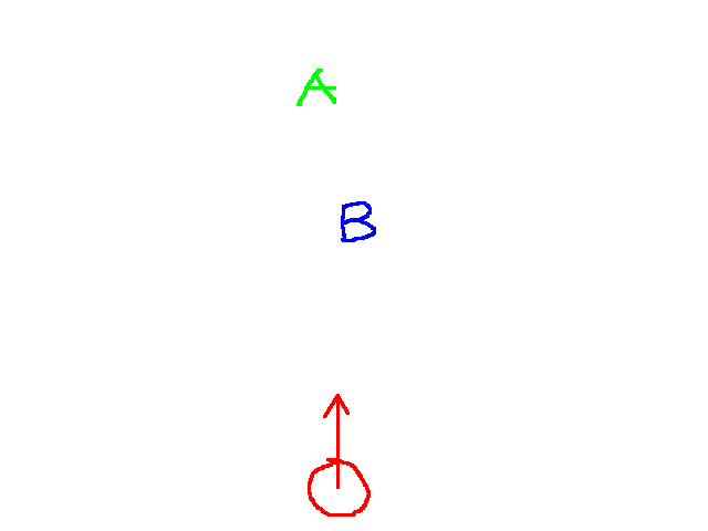
The red circle is the player. The arrow indicates the way the player is facing. The blue A and green B are sprites in our environment. In this case, we would want to see something like this in our 3D rendering:
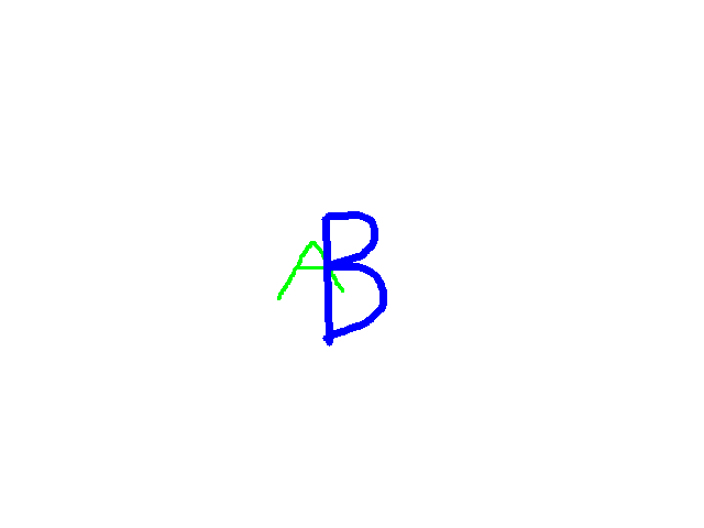
That is, the A is drawn behind the B. On the other hand, consider this scenario:
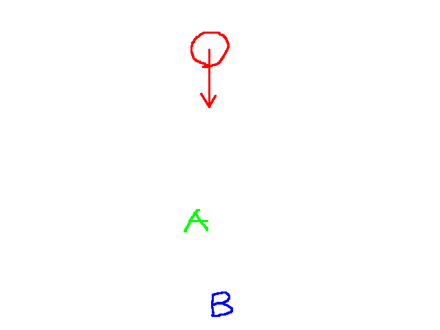
Then naturally, we’d want to see the sprites rendered like:
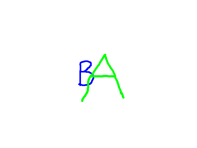
This is a rather quick and dirty mockup, but I think it does a sufficient job explaining the ideal behavior. In the first scenario, we would render the A onto the screen, then render the B over it. So when you perform quicksort, we want to sort from furthest sprite to closest sprite. That way, as we loop through each sprite to render them, we render the furthest first, then the closest over that.
Section 3: Computing Sprite Screen Coordinates
For each sprite, we now have to figure out where on the screen we render. The screen coordinates specifically tell us where the center of the sprite is. In my implementation, I did this computation even for sprites outside the view of the player, because we may be able to see a part of a sprite, even if its slightly off screen. I didn’t want to deal with special cases where a sprite is partially or wholly off screen.
Finding the screen coordinates of a sprite is not immediately intuitive. It essntially requires you transform the sprite’s world coordinates to screen coordinates. Some implementations require matrix transformations and a whole slew of linear algebra. Although this may be an intuitive approach to vector transformations, we won’t use that here. Instead, we’ll begin with some assumptions about walls and sprites in the world:
- As I detailed in the last post: everything is 64 pixels by 64 pixels in dimensions
- Everything is vertically fixed as I will explain below
The first point isn’t new, but coupling it with the second point is huge. When I say that everything is vertically fixed/centered, I mean the following graphic:
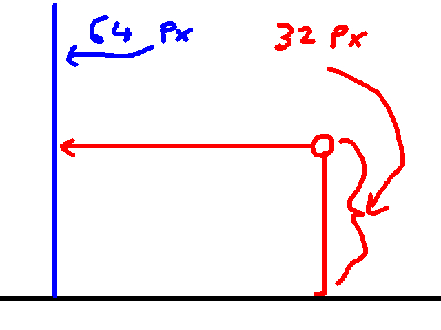
So the player is 32 pixels in height, but everything else is 64 pixels in height. Furthermore, everything is vertically fixed/centered. That is, no matter where anything in the world is, be it sprites or walls or what have you, it means that y coordinate of the center of everything is half of the projection plane’s height. Since my implementation assumes the projection plane has a height of 200, then the y coordinate of the center of everything on the screen is 100.
This means right off the bat, we already have the y coodinate of sprite’s screen position. All that remains to find is the x coordinate of the center of the sprite.
And let me emphasize this: the y coordinate of the center of everything is 100 only on the screen. This is not the case for world coordinates. This was something that threw me for a loop when I first started working on this. You have to remember that y in the world isn’t the same as y on the screen, since the screen is a 2D plane and the world is 3d-ish.
This is a much trickier problem, since we don’t have an obvious way to relate a sprite’s world position to the screen. We could do something similar to walls. For each column of pixels in our screen, fire a ray, and move it until it hits a sprite. However, since sprites are a lot less constrained as to where they can be in the environment, we’ll hit some nasty cases we’d have to handle.
Instead we’ll need to do a reverse computation to walls. With walls, we start with columns of pixels and find the world coordinates. This time, we know the world coordinates, and need to find the column of pixels we want to render.
For this, we’ll draw from trigonometry, and use the atan2 function. Essentially, given a vector, we can compute the angle formed between it and the x-axis. Suppose we’ve the situtation:
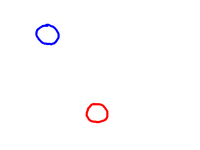
Where the red circle is of course the player, and the blue one is a sprite in the world. If we know the position of each, we can figure out the vector between them, which is the following:
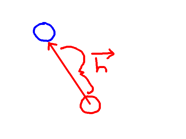
I would call this vector d for “difference” or perhaps i for “increment” (as Layne does), but I thought they would be confusing (we used d extensively in the previous article, and i is associated with imaginary numbers). Instead, we’ll use h. Computing h is a simple vector operation:
h.x = sprite.x - player.x h.y = sprite.y - player.y
Now why do we need this? Basically, we can compute the angle between the x-axis and h. Here is the graphic redrawn with the x-axis superimposed:
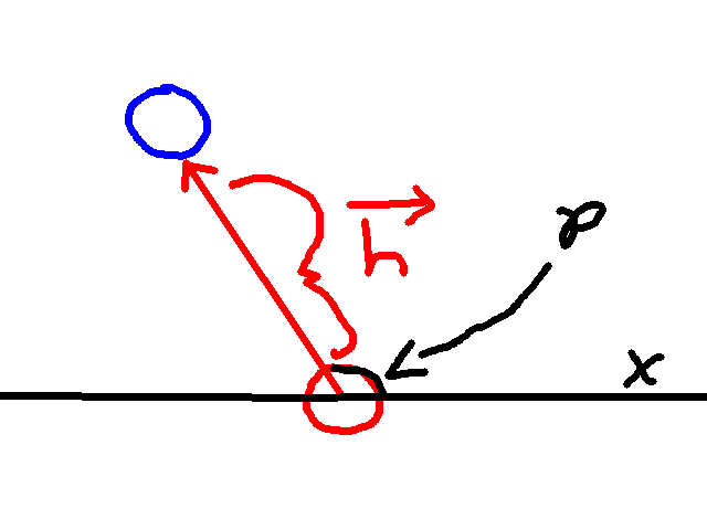
Also included is an angle p. This angle is the one we are interested in. To compute p we do the following computation:
p = atan2(h.y, h.x)
Note that typical implementations of this have the y coordinate as the first argument. Also, since our y axis is flipped, we need to negate this. Thus:
p = atan2(-h.y, h.x)
Then, since we are dealing in degrees, our resulting angle will be:
p = atan2(-h.y, h.x) * (180 / PI)
Finally, like all angles, we want to make sure this is between 0 and 360, so:
if p < 0:
	p += 360
if p > 360:
	p -= 360
So great, Liam. You made everyone solve for this angle p, but what was the point? Recall that there is a relationship between columns of pixels and ray angles. If our projection plane width was 320, and our field of view was 60 degrees, we could say that there was 60 degrees for 320 columns of pixels, or 0.1875 degrees per column of pixels. Similarly, you could say there was 320 columns of pixels for 60 degrees. Simplifying this would tells us there are about 5.33 columns of pixels for every 1 degree.
This relationship gives us a means convert say an angle to a corresponding column of pixels. Since the x coordinate of our sprite is a column of pixels, we just use this conversion factor on p and we’re all set, right? That is, we just need to do p * 320 columns of pixels / 60 degrees, right?
Not quite. Let’s draw h, p, and the player’s field of view in one graphic:
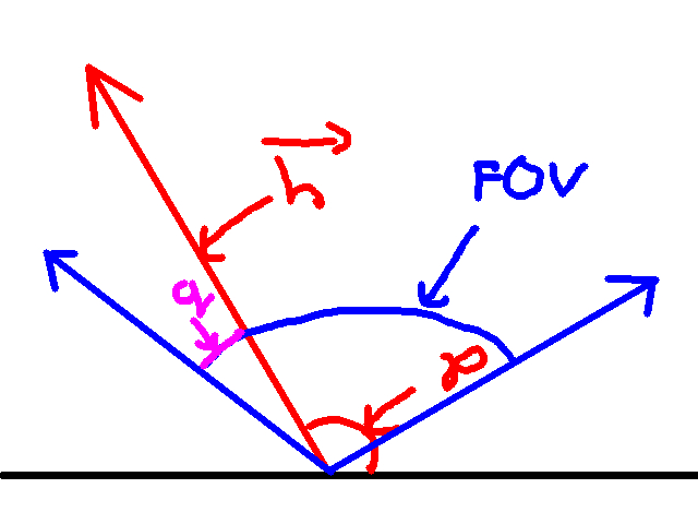
The black line is the x axis, h and p are in red, and the blue lines represent the max and min angles of the player’s field of view.
Notice that I included a new angle q, in purple. What is q? This angle is the difference between the leftmost angle of the player’s field of view and p. Since we know the player’s rotation, and his field of view, we can calculte the leftmost angle of the field of view as follows:
player_rotation + (fov / 2)
And this angle represents the angle corresponding to the leftmost column of pixels on the screen. Suppose the player’s field of view is 60, then there are 60 / 2 = 30 degrees of view to the left and right of the player’s rotation. I think a graphic is quite instructive here:
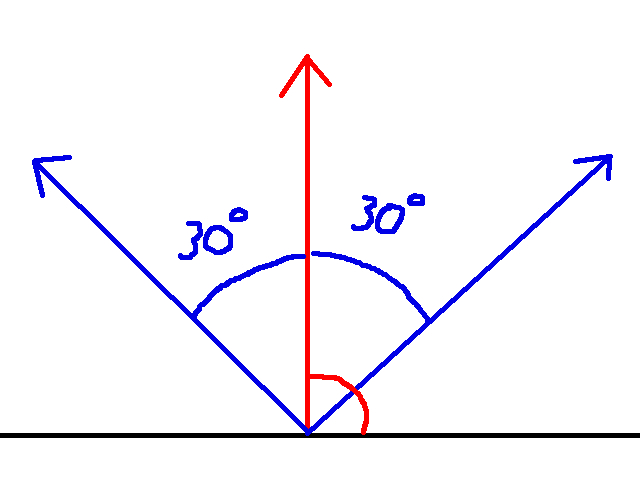
Where the red line is the player’s rotation. The field of view is 60, and thus there are 30 degrees of view to the left and right of the player. Note that the picture implies the player’s rotation is 90 degrees. This is for the sake of the graphic. This relationship holds regardless of the player’s rotation.
So anyways, why does knowing the leftmost angle of the field of view do for us? Well let’s draw the player’s field of view but with the angle p included:
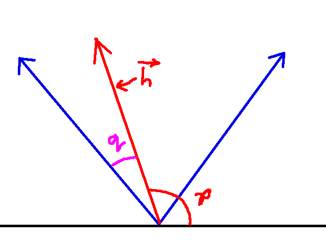
Also included is the angle q. Recall that p is the angle between the player and the sprite we want to render. Now, if the leftmost angle of the field of view corresponds to column 0 of the projection plane, then q is the angle that corresponds to another column of pixels on the screen. In other words, q is the angle that connotes the x coordinate of the sprite’s center on the screen. If we use our conversion factor from earlier, we can transform q into a column of pixels:
sprite_screen.x = q * (proj_plane_width / field_of_view) = q * (320 / 60)
There’s still a problem here: how do we compute q? There are some corner cases that make this harder than one would think, so I’ll now spend some time discussing this. For the most part, we compute q with the following computation:
q = player_rot + (fov / 2) - p
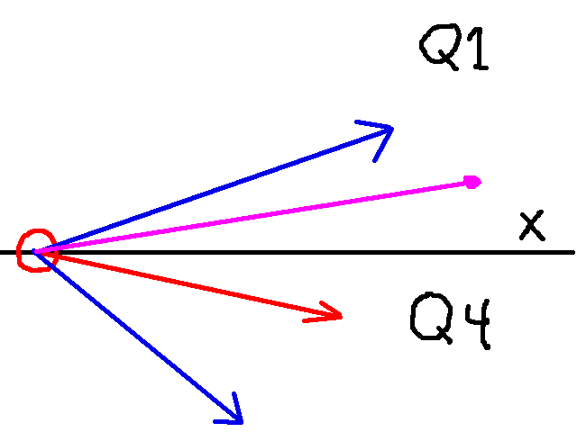
The player_rot + (fov / 2) gives us the leftmost angle of the entire field of view. Then subtracting p gives us the difference. However, suppose we have the following scenario:
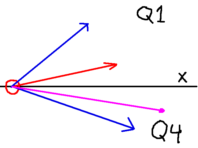
Where the red arrow is the player’s rotation, the two blue arrows represent the player’s field of view, and the purple line is the vector h. This implies p is in quadrant 4, but the player’s rotation is in quadrant 1. If we compute q above, we would get something like the following:
q = [Angle between 0 and 90] - [angle between 270 and 360]
Which means q will be negative. As such, we need to add 360 after computing q to get the correct angle. Thus:
q = player\_rot + (fov / 2) - p

if player rot in quadrant 1 and p in quadrant 4:
	q += 360
Now on the other hand, suppose we’ve this scenario:
Then we have the opposite case, that is:
q = [angle between 270 and 360] - [angle between 0 and 90]
Which means that we need to subtract 360. Thus:
q = player\_rot + (fov / 2) - p

if player rot in quadrant 4 and p in quadrant 1:
	q += 360
And with that, we’ve got all the pieces to find the screen coordinates of the center of the sprite! Let’s go ahead and put it all together. I’ll write it as psuedo-code since we need to do if statements for the proper computation
h.x = sprite.x - player.x
h.y = sprite.y - player.y

p = atan2(-h.y / h.x) * (180 / PI)

if p > 360:
	p -= 360
if p < 0:
	p += 360

q = player_rot + (fov / 2) - p

if player_rot in quadrant 1 and p in quadrant 4:
	q += 360
if player_rot in quadrant 4 and p in quadrant 1:
	q -= 360

sprite_screen.x = q * (projection_plane_width / fov)
sprite_screen.y = 100 (projection_plane_height / 2 = 200 / 2 = 100)
Section 4: Determine the Sprite Scale
We now have the sprite’s position on the screen. The last thing we need to do is scale it. Recall that for finding the height of a wall slice on the screen used the following relationship:
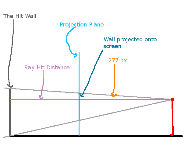
That is:
projected_wall_height / dist_to_proj_plane = 64 / ray_hit_dist
The same relationship holds for sprites. That is:
projected_sprite_height / dist_to_proj_plane = 64 / distance_to_sprite
And thus:
projected_sprite_height = dist_to_proj_plane * 64 / distance_to_sprite
Since the distance to the projection plane is precomputed (see Part 1), then the final equation is:
projected_sprite_height = 277 * 64 / distance_to_sprite
Note that since every sprite is a square (a 64 pixel x 64 pixel square), the projected srite width is the same as the projected sprite height. So a summary of our computations is:
- projected_sprite_height = 277 * 64 / distance_to_sprite
- projected_sprite_width = projection_plane_height
Section 5: Notes about rendering and Conclusion
At this point, you know the where to render the sprite to the screen and the scale of it. The only thing that remains is the actually drawing it. I won’t go into too much detail here like the other sections, but just a few remarks.
Essentially, you need to render the sprite as a series of columns, not unlike walls. Since you know the location of the center of the sprite on screen and its scale, computing where each column of the sprite on the screen is, and what part of the sprite to render isn’t too bad. I would look at my code to see how that’s done.
More importantly, we want to make sure we only render columns of sprites not obscured by walls. Essentially for each column of screen pixels, you want to keep track of two things:
- Did the ray associated with this column of pixels hit a wall?
- If it did, what was the distance
Then, when you wish to render a column of sprite pixels, you do so under two circumstances:
- Did the ray of this column actually hit a wall? If not, we can render our sprite column.
- If it did hit a wall, we render the sprite column only if this distance to the sprite is less than the wall.
At this point, you shoud have all of the theoretical background required to do “sprite casting”, as its coloquially called sometimes. If this high level explanation was not enough, I would check out my code, and some of the other sources I have below. In the next article, we’ll detail floor, ceiling, and sky casting. Thank you for reading!