Liam Wynn
This is my site. Here, I make neato projects and blog posts.
Implementing a Ray Caster Part 3: Floor, Ceiling, and Sky Rendering
Welcome back, everyone. In this article, I will discuss how to render floors, ceilings, and skies.
For floor and ceiling rendering, I based my implementation off of Permadi’s work. Here is his article detailing floor and ceiling rendering.
Why do we want to render floors, ceilings, and skies?
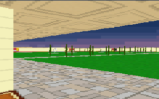
I suppose this question answers itself. Nonetheless, I’ll take an opportunity here to present two screenshots from my engine. The first one has floors, ceilings and sky present. The second, of course, does not:
The first image:
The second image:
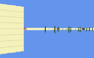
I don’t think there’s much else to say here other than being able to render floors, ceilings, and skies dramatically improve the environments you can depict. Now let’s jump right into it!
Part 1: Floor Casting
Floor casting is an inverse operation to ray casting, in some sense. That is, you begin with pixels on the screen, project them into the world, and then render floors, if the resulting location has a floor texture to render.
Why do we start with the screen pixels? I suppose you don’t have to, but it’s more effecient. If you started with world coordinates, you could only reasonably do so as rays are being casted to check for walls. So at every step of your ray casting, you would check if a floor pixel is present. However, recall that the ray casting goes between gridlines. What about the points in between gridlines? No no, this won’t do.
Instead, let’s take advantage of the fact that there is no vertical variation in our levels, and everything is vertically centered. What does this mean for floors? It means they’re always below wall slices that we render when performing ray casting. In other words, our algorithm looks like the following for a single column of pixels:
1. Cast a ray
2. If ray does not hit a wall: return
3. Otherwise, render wall slice ray hits.
4. For each pixel below the bottom of the wall slice on the screen:
	1. Project pixel location onto world.
	2. Render pixel of floor texture at screen position, but only
	if there is a floor texture to render.
So in my implementation, we only render floors if a ray actually hit a wall. Naturally, this is a limitation of my engine, but it does mean floor rendering is about as effecient as can be.
So the crux of floor casting is projecting a screen position onto the world. Let’s figure out how to do that.
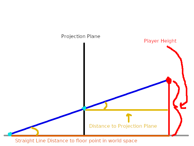
Here is a graphical representation of our goal:
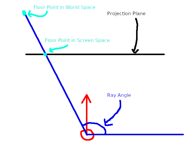
Where the red circle with the arrow is the player. We know the player’s rotation, the ray angle, and the screen space position of the floor. What we want is the floor pixel in world space. Since we do not know this, we do not know the distance of the ray.
Like every problem, we can employ trigonometry to help us here. What if we had the straight line distance to the floor point in world space? That is:
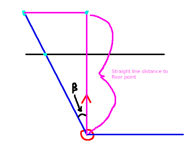
I’ve also included an angle beta, which is the ray angle relative to the player. To compute beta, do the following:
Beta = abs(ray angle - player rotation)
Now if we knew the straight line distance to the floor point in world space, then we could employ Soh Cah Toa to get the “true” distance to the point. Let’s first find the straight line distance to the point. Let’s re-render the above but from the side:
Now we see a relationship between several values that we know and the desired value that we wish to solve for. Using the Similar Triangle Formula, we can represent this relationship as:
straight line dist to floor point in world space / dist to projection plane = player height / r
Now wait a minute, what is r? Graphically, r is this value:
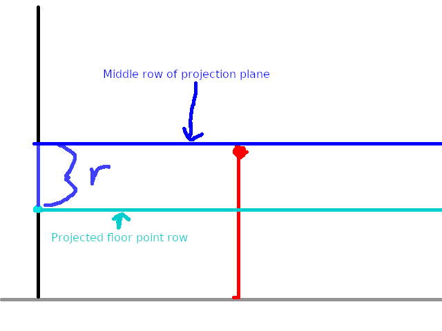
Where the black line is the projection plane. So r is not the row of floor point in screen space (the floor point’s screen y coordinate, in other words), but the difference between the floor point row and the middle row of the projection plane. This the projection plane height / 2, or 100 in my implementation Putting everything together that we have so far, we get:
- r = projected floor point row - center row of projection plane = projected floor point row - 100
- straight line dist / dist to proj plane = player height / r
- so, staight line dist / 277 = 32 / r
- thus, straight line dist = 32 * 277 / r
And now we have the straight line distance to the floor point in world coordinates. Let’s call that s, and get a new visual for our problem:
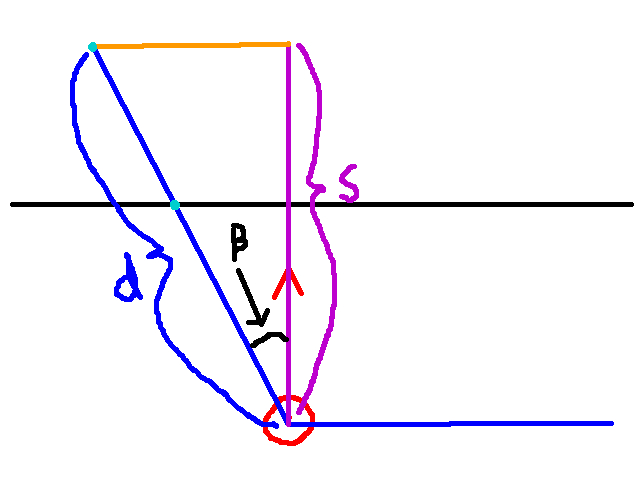
We know s, and the angle Beta, and we want d. With d as the hypotenuse of a triangle formed with s (the adjacent leg), we can use the Cah in Soh Cah Toa as follows:
- Cos(Beta) = s / d
And then solving for d, we get:
- d = s / Cos(Beta)
And there we have it! We now have the true distance from the player to the floor point in world space. All we have left is to take our ray angle and newly found distance and compute the x and y coordinates of the floor point. We can do so with these:
- floor_point.x = player.x + cos(alpha) * d
- floor_point.y = player.y - sin(alpha) * d
First, why do we add the player’s x and y? Because the distance d is from the player to the floor point. To get the actual world coordinates, we need to add the player’s position. Next, why do we use alpha? The reason is two fold. First, Beta is the ray angle relative to the player. And second, we use alpha because alpha is the ray angle that corresponds to the column of pixels we are doing ray casting for. Finally, recall that our y coordinate is flipped. Hence, we subtract sin(alpha) * d from the player y.
And now you have the floor position itself, all that is really left to do is choose what pixel from the floor texture you want to render. That is dependent on several parameters specific to your needs, in my case, I simply mod the floor point x and y by 64 since every texture is 64 px by 64 px. Like wall and sprite rendering, I’ll leave this out of this post. If you’re interested, check out my implementation here.
Part 2: Ceiling Casting
Next, let’s render ceilings. As it turns out, the way we do ceiling casting is the exact same way we do floor casting! That’s right: none of the math is different. There is only one subtle change to the algorithm for floor casting that we make. See if you can spot it:
1. Cast a ray
2. If ray does not hit a wall: return
3. Otherwise, render wall slice ray hits.
4. For each pixel above the top of the wall slice on the screen:
	1. Project pixel location onto world.
	2. Render pixel of ceiling texture at screen position, but only
	if there is a ceiling texture to render.
On step 4, we iterate through each pixel above the topmost pixel of the wall slice on the screen, and do our reverse projection to get the ceiling point in world space.
There is a cool time saving technique we can use so we can do floor and ceiling casting in one go. Suppose you computed the floor point in world space for some screen pixel f. Now f.y (the row of our screen pixel) is some number of pixels under the middle of the screen, say n. Graphically, that is as follows:
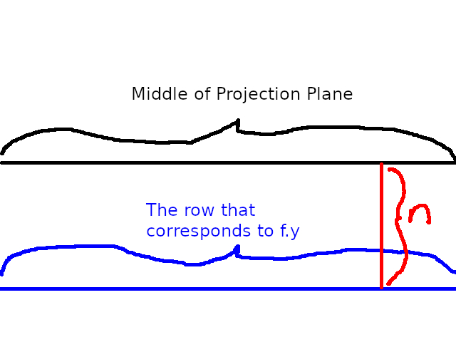
That is, n = f.y - (projection plane height / 2) = f.y - 100
Now since all the calculations we do for the floor are the same for the ceiling, we need only to find the ceiling screen pixel c that corresponds to f. Since c and f are in the same column, then c.x = f.x. If f.y is n units below the middle of the projection plane, then:
c.y = 100 + n
And now all the floor casting you did for f you’ve done for c!
Part 3: Sky Casting
In my ray caster, sky rendering the first thing I do. In fact the order of things goes like this:
1. Render skies
2. Render walls
3. Render floors and ceilings
4. Render sprites
There’s a little bit more subtlety to it than this, but this is more or less the drawing order. It would seem counter-intuitive to render the skies first before anything else. However, when we render pixels to the screen, we want to make sure the wall, floor and ceilings are not rendered under the sky. Thus, we render the sky first, and then overwrite whichever pixels we need with the walls, floors, and ceilings (then render the parts of sprites we want over the walls, floors, and ceilings).
So how do we render the sky? Essentially I did a cheap method. Basically, I take a wide picture and wrap it around the level in some sense. Since my projection plane is 320 pixels, I figured a texture twice that in width would be sufficiently large. So now I have 640 columns of pixels. If I have 360 degrees to represent a circle, then we can define a conversion factor. That is:
640 columns of pixels / 360 degrees
Now I know that it would be much better to have 360 columns of pixels, that way the conversion factor is much simpler. At the time, I was in a crunch period to finish my project and so I didn’t put much thought into this conversion factor.
Anyways, what does this conversion factor do for us? Well basically it helps us do the sky rendering algorithm, which is:
For each column of pixels on the screen:
1. Compute the corresponding ray angle alpha (adjust alpha to be between 0 and 360)
2. The column of the sky texture to render is thus alpha * 640 columns of pixels / 360 degrees
Now for the column we are going to do ray casting on, we know the corresponding column of pixels in the sky texture. As for the height of the sky texture, I just made it 200 pixels, which is the same as the height of the projection plane. There is no reason to make it any larger or smaller, for obvious reasons.
Concluding Remarks
Anyways, I hope you found this informative. This is more or less the math for every feature I implemented for my rendering engine. I will be back with a fourth and final part, wherein I detail various optimization tricks I did for this.